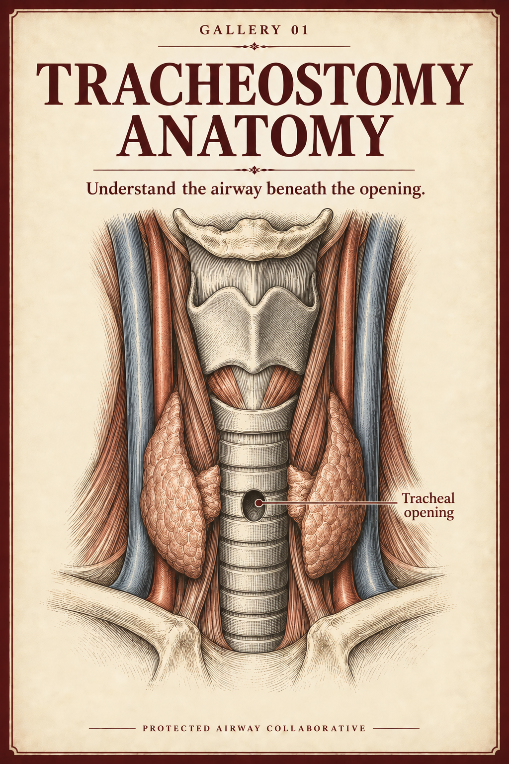
01
Gallery
Airway Anatomy
Opening, tract, altered airway routes, and the structures immediately beside them.
Poster 611 · PAC, 2026
AI-assisted illustration · Interpretive anatomical cutaway
Tracheostomy Airway Safety Lab · Exhibition entrance
Explore the altered anatomy and the device. Then rehearse your response to tracheostomy emergencies, online or in the Practice Studio.
Playback is unavailable. Open the captioned film ↗
1:01 · Soundscape with on-screen dialogue.
Meet Sarah, your virtual guide. Then scroll down to begin.
Created by PAC, 2026. Fictional virtual guide using ElevenLabs’ Sarah – Warm and Grounded voice and designed sound. Owner-supplied interpretive poster; playback texture made with OpenAI image generation. Artwork is not a verified device diagram.
Quiet background room activity; no music.
Sarah: Hi, I'm Sarah, your virtual guide to the Tracheostomy Airway Safety Lab. I'm glad you're here.
Sarah: A tracheostomy changes the airway. The tube adds a device you need to understand. This space helps you put those two pieces together, and build confidence through practice.
Sarah: Start with airway anatomy. Then explore Tools of the Trade: the tubes, their parts, and the differences that matter.
Sarah: Next, put that understanding to work in our emergency cases. Make your next move before the explanation. Then explore the debrief galleries and see what you'd change.
Sarah: You can work through the cases online, or bring them into our Practice Studio with the advanced tracheostomy trainer. Practice on your own, or work with a coach.
Sarah: The aim is a clearer understanding of the airway and the device, and a more deliberate response when common emergencies happen, including knowing when to call for help.
Sarah: Ready? Scroll down, start with the anatomy, and we'll take it from there.
Choose your way in
The recommended route moves from anatomy to the tools of the trade, then into an unannounced emergency case.
Exhibition Map
Gallery
Opening, tract, altered airway routes, and the structures immediately beside them.
Poster 611 · PAC, 2026
AI-assisted illustration · Interpretive anatomical cutaway
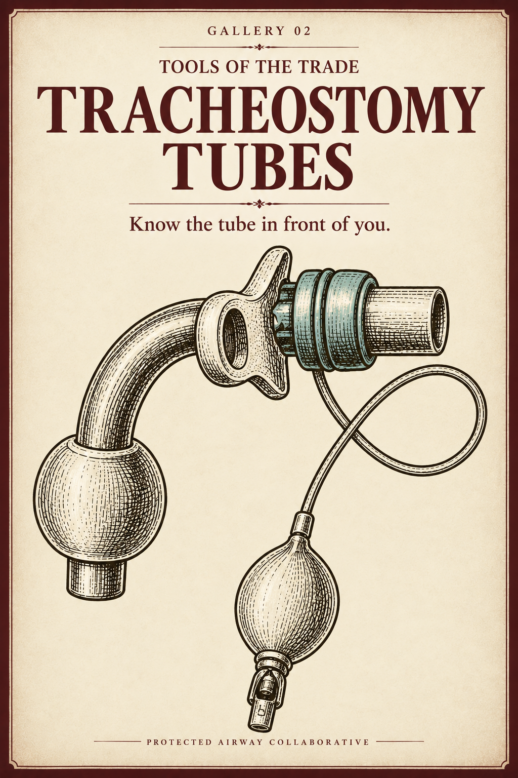
Gallery
Tracheostomy tubes, components, markings, device variation, and physical object handling.
Poster 612 · PAC, 2026
AI-assisted artwork · Not a verified device diagram
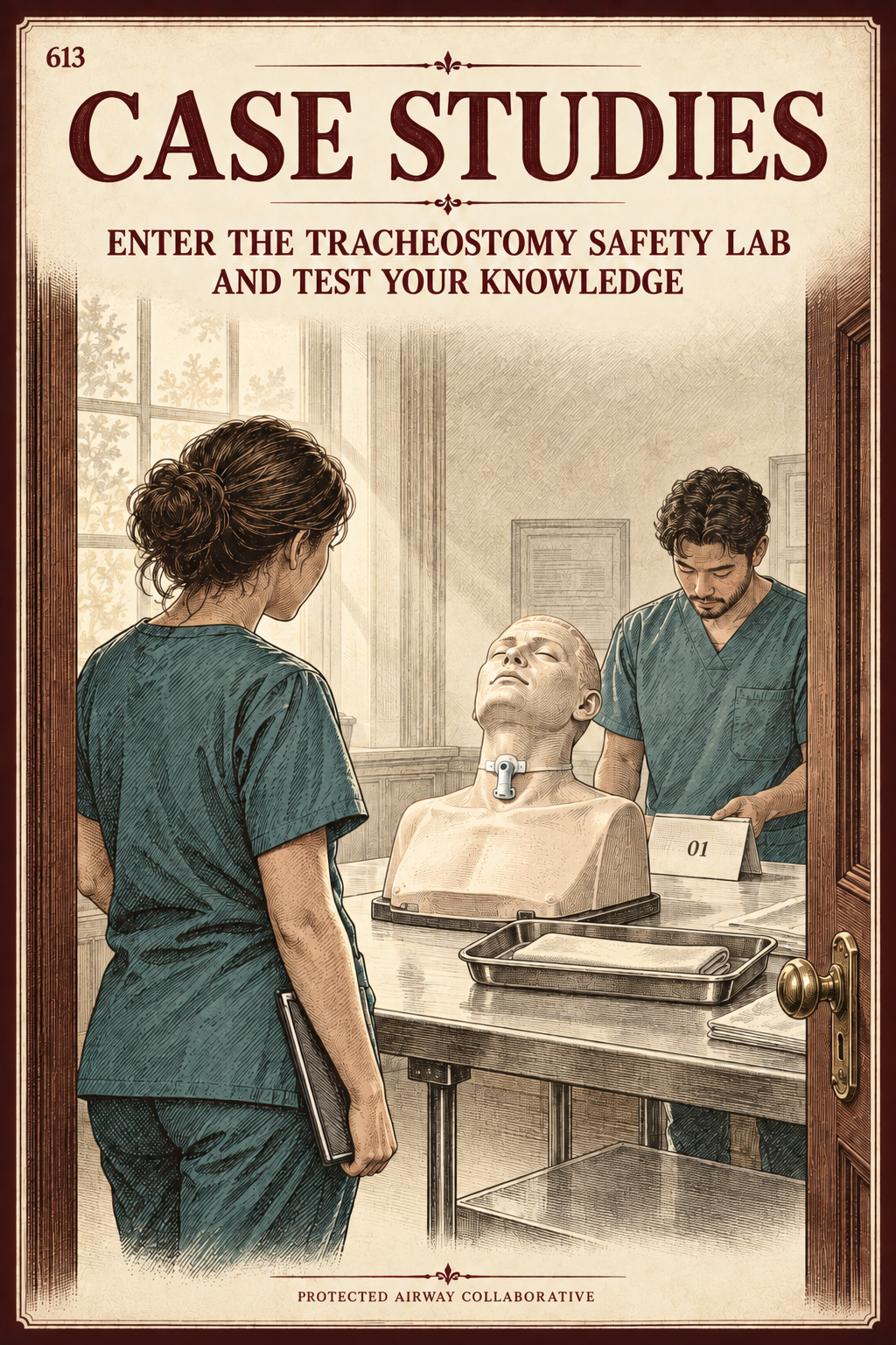
Practice Studio first · debrief Gallery second
Five numbered cases. Each attempt leads to its own explanation, Object study, and return to the relevant anatomy or equipment.
Poster 613 · PAC, 2026
AI-assisted illustration · Imagined training scene
Installation guide · physical layer
The final guide will name the trainer, tube set, scenario objects, starting arrangement, observable finish line, reset, cleaning, support route, and screen-to-hands handoff. The digital experience does not claim the physical work occurred.
Gallery 01 · Airway Anatomy
Trace the route to the lungs. Explore what tracheostomy and total laryngectomy change—and why the tissues around the opening matter.
Five rooms · Adult anatomy
Playback could not start. Open the scene directly →
Anterior anatomical view. Overlying tissues removed and thyroid isthmus divided to expose the trachea.
AI-assisted illustration created for the Protected Airway Collaborative. Interpretive anatomical cutaway.
Look closer0:42 · Soundscape with on-screen dialogue.
A patient arrives with a displaced tube. The team has not yet confirmed his surgical anatomy.
Created by PAC, 2026. Fictional simulation with ElevenLabs synthesized voices and designed sound.
Stretcher wheels approach. Brakes click. Low staff voices, a distant indistinct announcement, and quiet labored breathing.
EMS We've got a patient with a displaced trach tube. Hypoxic, barely responding. We don't have his surgical history.
Team leader Oxygen to his face and stoma now. Get ready for a definitive airway.
Nurse Oxygen's on. Ready to move? One, two, three.
Sheets shift as the team transfers the patient.
Resident — Tim He's not moving enough air. I'll get set up to intubate.
Team leader Wait. We don't know if this patient has had a total laryngectomy. If he has, we won't be able to intubate from above. We need to know before we make our next move.
Equipment moves beside the bed.
Nurse Pediatric mask and bag ready.
Team leader Let's check the tube and stoma. Don't bag through a displaced tube. Tim—get his operative note.
Resident — Tim On it.
Department activity and breathing continue, then fade.
Gallery 01 · Room 01
Trace the airway before surgery changes its route.
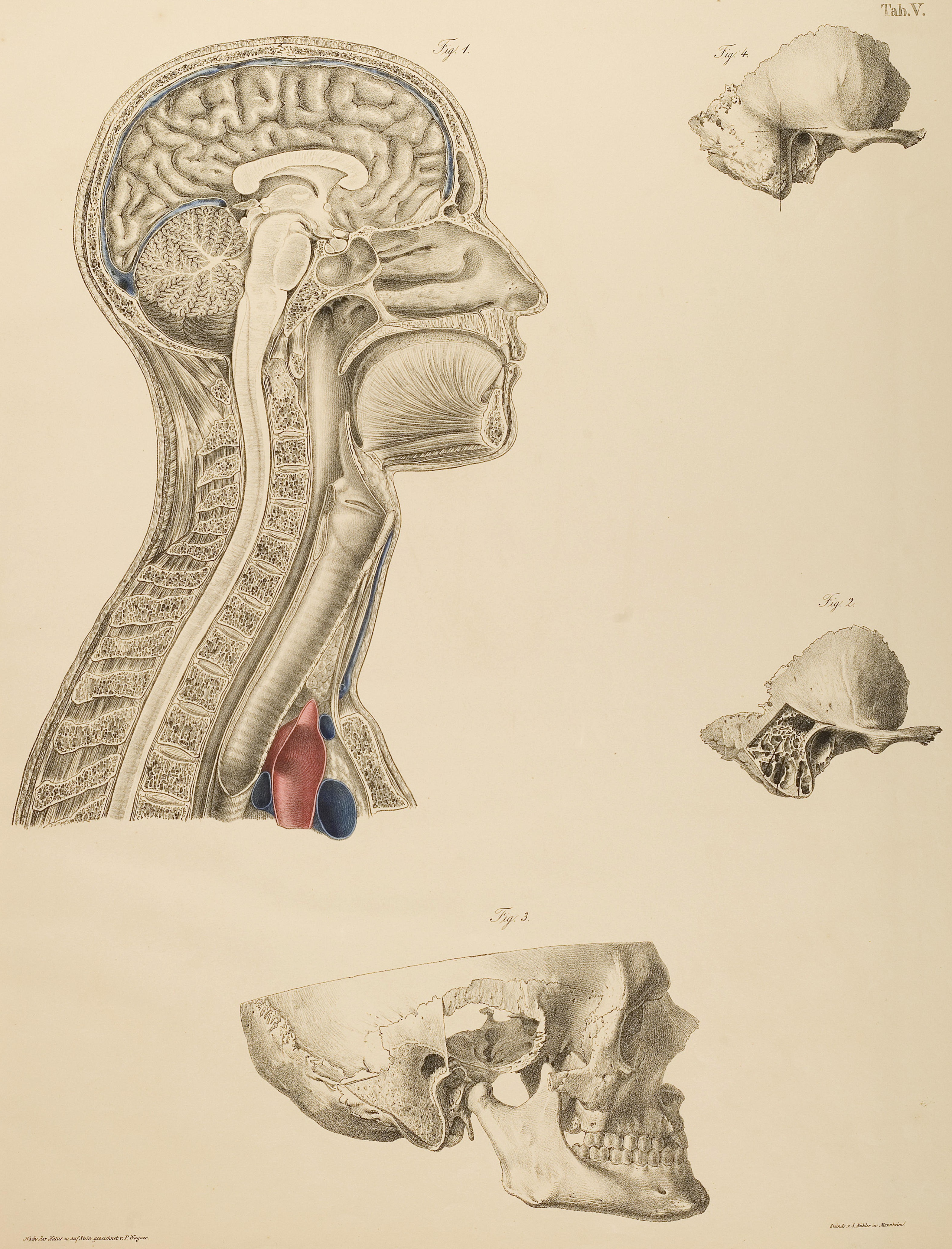 Look closer
Follow the large profile at left from nose and mouth toward the larynx. The carina and bronchi lie beyond this view.
Anton Nuhn; illustrations by Franz Xaver Wagner. Chirurgisch-anatomische Tafeln, Plate V ↗. Digital reproduction by Double-M, via Wikimedia Commons ↗, CC BY 2.0 ↗. Unmodified.
Historical illustration for anatomical orientation. Teaching interpretation pending clinical review.
The routes share the pharynx, then diverge. The esophagus lies behind the trachea and carries food toward the stomach. Swallowing protects the airway through coordinated movement and closure—not the epiglottis alone.
Locate the larynx before comparing the operations.
Next · Compare the connectionsGallery 01 · Room 02
Compare a side opening into the trachea with an end stoma after total laryngectomy.
A · Tracheostomy
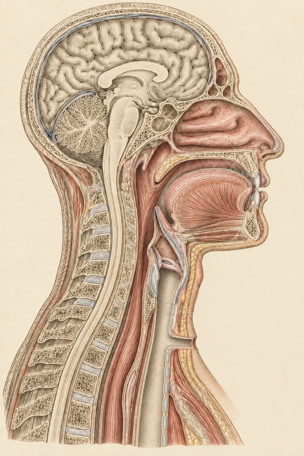 Look closer at the tracheostomy
The larynx remains above the side opening. The original condition may still obstruct the upper airway; equipment is omitted here.
Anatomical continuity is not proof of patency.
Created by PAC with AI assistance after Anton Nuhn / Franz Xaver Wagner, Plate V, c. 1846. Source reproduction by Double-M, Wikimedia Commons, CC BY 2.0. Contemporary digital adaptation: recomposed section, reinterpreted tissues and added tracheostomy. Not a historical plate.
Illustration draft · Anatomical review pending.
B · Total laryngectomy
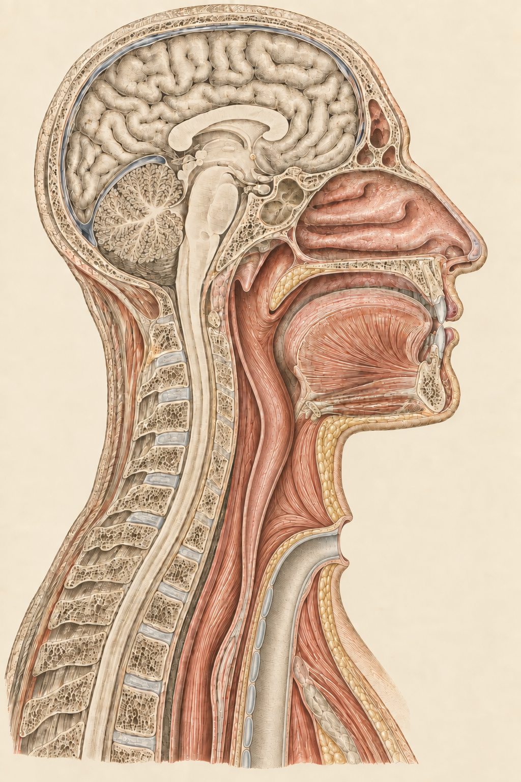 Look closer at the laryngectomy
The larynx is removed and the trachea ends at the neck. There is no normal airway connection from the mouth or nose to the lungs.
Created by PAC with AI assistance after Anton Nuhn / Franz Xaver Wagner, Plate V, c. 1846. Source reproduction by Double-M, Wikimedia Commons, CC BY 2.0. Contemporary digital adaptation: reinterpreted tissues and total-laryngectomy configuration. Not a historical plate.
Illustration draft · Anatomical review pending.
“Total” matters. Do not apply this anatomical model to every partial laryngeal operation. A tube’s appearance—or the patient’s ability to speak—does not establish the surgical anatomy.
Identify the operation. Then consider which routes are actually usable.
Next · From skin to tracheaGallery 01 · Room 03
Locate the same landmark at the surface and beneath it.
Human cadaver photographs · Head end above, chest end below
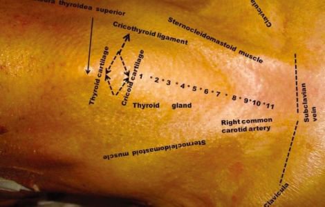
Gulsen and colleagues, 2010 · Figure 1
The numbered rings are projected onto intact skin. They do not show an open tract or the tracheal lumen.
Reproduced with permission from Gulsen et al., J Korean Neurosurg Soc. 2010;47:174–179, Fig. 1. ©2010 The Korean Neurosurgical Society.
Look closer at the surface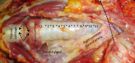
Gulsen and colleagues, 2010 · Figure 4
Overlying tissues are removed or displaced. Compare the exposed anterior trachea with the thyroid gland beside it and the labeled right common carotid artery.
Reproduced with permission from Gulsen et al., J Korean Neurosurg Soc. 2010;47:174–179, Fig. 4. ©2010 The Korean Neurosurgical Society.
Look closer beneath the surfaceThyroid cartilage → cricoid cartilage → tracheal rings. The thyroid gland is a separate structure. The cricothyroid membrane lies between the two cartilages; a tracheostomy enters below the larynx, at a different site from a cricothyrotomy.
Complete photographs, turned a quarter-turn clockwise. Views are not matched to an exact scale; not a surgical sequence or an incision-level guide. Original study and figure captions ↗
PAC Object TR-004-L · Schematic location markers created by PAC, 2026. Separate from the original photographs; not tissue boundaries. Anatomical placement review pending.
Skin, subcutaneous tissue and strap muscles overlie the trachea; the thyroid isthmus crosses its front. The route varies with anatomy and formation technique. The esophagus lies behind the trachea, while the innominate artery relates to its lower anterior surface.
These anterior views do not show the tracheal lumen, membranous posterior wall or esophagus. Tracheal cartilage supports the anterior and lateral walls.
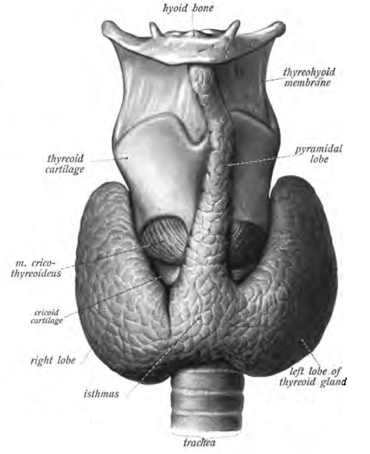
From Johannes Sobotta’s Atlas and Text-book of Human Anatomy, Fig. 444.
The thyroid gland and thyroid cartilage are different structures. Here the gland’s isthmus obscures part of the upper trachea. The upward extension labeled “pyramidal lobe” is variable anatomy, not a feature to expect in every patient.
Public domain. Source: Wikimedia Commons, scan of Sobotta’s 1906 atlas ↗. Complete original plate, unchanged.
Look closer at the atlas plateThe external opening and the airway lumen are different locations. Next, consider how the tract between them changes.
Next · The tract changesGallery 01 · Room 04
A new opening and an established tract are not the same structure.
Fresh tracheostomy · Operative photographs
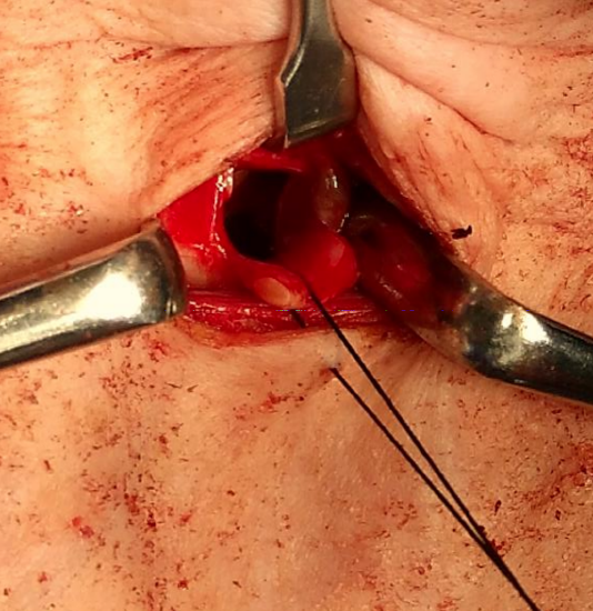
The tracheal flap is reflected downward, with a traction suture attached. This is a view during formation of the opening—not an established skin-to-trachea tract.
Courtesy of Johan Fagan, Open Access Atlas of Otolaryngology, Head & Neck Operative Surgery, University of Cape Town. Figure 8, via Medicine LibreTexts. Reproduced with permission. Unmodified.
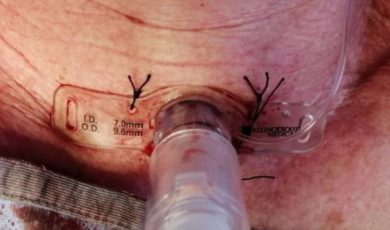
These sutures secure the tube at the skin; they are different from the flap’s traction suture. The flange covers the opening, leaving the deeper tract out of view.
Courtesy of Johan Fagan, Open Access Atlas of Otolaryngology, Head & Neck Operative Surgery, University of Cape Town. Figure 11, via Medicine LibreTexts. Reproduced with permission. Unmodified.
Both photographs show the operative or newly formed setting. Neither documents a healed tract. The next exhibit is a separate clinical example, not a follow-up of these photographs.
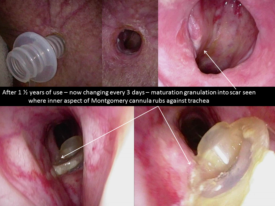
Find the tube-free opening in the upper-middle photograph. This separate clinical example documents 18 months of Montgomery-cannula use; the internal views show scarring where the cannula contacts the trachea.
Source: University of Iowa, Iowa Head and Neck Protocols · Hood Stoma Stent, image 5. © The University of Iowa. Complete source montage, unmodified. Local review only; reuse permission pending.
After the tube comes out, the stoma can narrow or close within hours. A newly formed tract can close more quickly than an established one. Complete airtight healing may take days; that does not mean a tube-sized passage remains available.
Ask both when the tracheostomy was formed and how long the tube has been out. Surgical and percutaneous tracts differ; healing, depth and previous tube-change difficulty also matter.
In a small adult cohort after decannulation, median time to airtight closure was 6.5 days, with a range of 1–22 days (28 patients analyzed). The study measured wound healing—not how long a tract remained usable for reinsertion. These numbers are not a safe waiting period.
Christiansen et al., 2022 · Read the study ↗A tube can enter the anterior soft tissues rather than the tracheal lumen. The neck opening may still be visible while the intended path is lost or misaligned.
A calendar threshold alone cannot establish that reinsertion is straightforward. Recent or uncertain tracts require particular caution and appropriately experienced airway help.
After tracheostomy · Scar revision
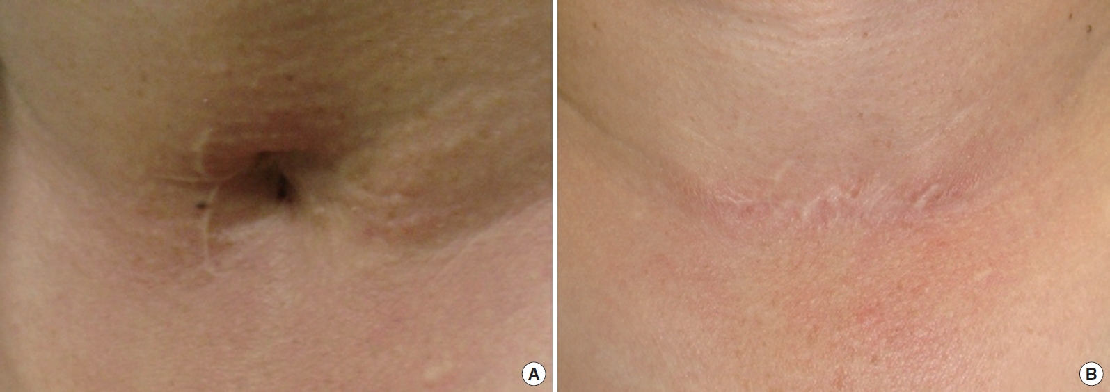
A: A depressed scar after tracheostomy. B: The same site 16 months after surgical scar revision. This pair shows a surgical outcome, not spontaneous stoma closure or how quickly the tract closes after tube removal.
From So-Min Hwang, Sang-Hwan Lee, Hong-Il Kim, Yong-Hui Jung and Hyung-Do Kim, Figure 3 · Original article, 2013. © The Korean Society for Aesthetic Plastic Surgery. CC BY-NC 3.0. Supplied reproduction unmodified.
Keep the patient’s condition and the tract’s condition as separate questions.
Next · What the bypass changesGallery 01 · Room 05
Air entering at the neck bypasses the nose’s warming, filtering and humidifying surfaces.
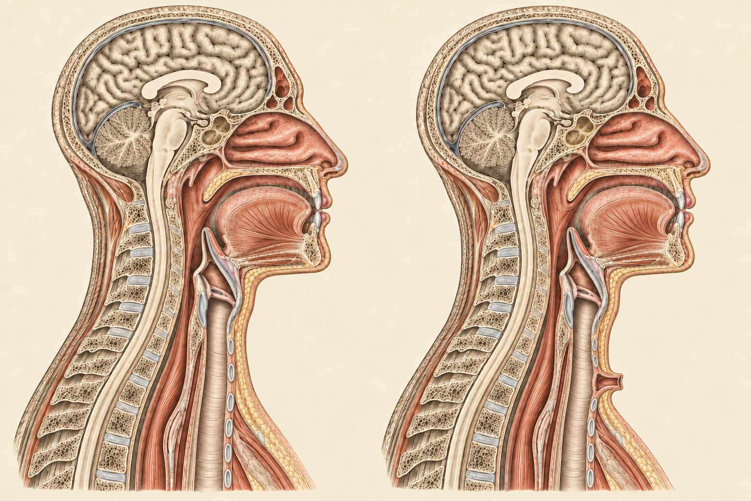
01 · Through the nose The nasal lining helps warm, filter and humidify inspired air before it reaches the lower airway.
02 · Through the neck Air entering through a tracheostomy bypasses that upper-airway conditioning. The larynx remains above the opening.
Created for the PAC Collection using OpenAI image generation, 2026; PAC interpretive overlays. Based on PAC’s Room 02 study after Nuhn / Wagner, Plate V, c. 1846; source reproduction by Double-M, Wikimedia Commons, CC BY 2.0. Reconstructed paired anatomy with added paths; not a historical plate. Anatomical review pending. Paths are schematic; the oral route and equipment are omitted.
Examine the comparison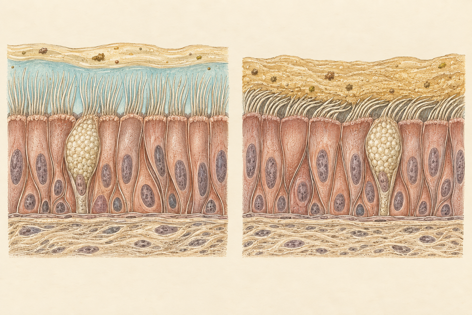
Left: adequately hydrated surface. Right: reduced surface hydration. Compare the space around the cilia and the mucus above them.
Created for the PAC Collection using OpenAI image generation, 2026. Schematic illustration, not a micrograph or to scale; anatomical review pending.
Examine the liningMove closer · The airway surface
Cilia help move mucus toward the pharynx. Inadequate humidification can make secretions harder to clear and impair this transport.
The right-hand study shows a possible consequence of reduced hydration—not the inevitable condition of an airway with a tracheostomy.
Humidification equipment belongs in Gallery 02. Here, identify the function it needs to support.
Study reference · Button et al., 2012 ↗Voice with a retained larynx requires air at the vocal folds. After total laryngectomy, speech can be restored without restoring the normal airway connection.
Swallowing difficulties remain possible; communication and swallowing need individual assessment.
Next · Gallery 02 · Tools of the Trade
Examine the tubes and components that work within this anatomy.
Gallery 02 · Tools of the Trade
You have considered the route through the neck. Now inspect the appliance that occupies it: the components, markings, and connections you will need to recognize when a case begins.
Playback could not start. Open the scene directly →
0:52 · Soundscape with on-screen dialogue.
A nurse and trainee get ready to receive a tracheostomy patient.
Created by PAC, 2026. Fictional simulation with ElevenLabs synthesized voices and designed sound. Poster and paper plate made with OpenAI image generation; interpretive artwork, not a verified device diagram.
View the complete posterHospital-floor activity. A distant overhead page: “Patient transport, please call the nurses’ station. Thank you.”
Nurse We've got a patient coming up from the ICU with a tracheostomy. Let's get ready before they arrive. Have you worked with a trach tube before?
Trainee I've seen them, but honestly, I don't know much about them. Aren't they basically plastic tubes? They look pretty straightforward.
Nurse They can look that way. But there are different designs, and the parts matter. Some patients have a lot of secretions. Those can block the tube. Bleeding can complicate things, too. If someone depends on that tube to breathe, you don't want to be learning how it works when they suddenly can't.
Trainee Oh. I hadn't really thought of it like that. Can we look at one?
Nurse Absolutely. Let's go over the tube and its features, so you know what you're looking at and how the parts work together. We'll talk about day-to-day care later. For now, let's get familiar with the device.
Gallery 02 · Room 01
At first glance, a Shiley tracheostomy tube looks deceptively simple. Look closer, and each component reveals a purpose. The curve of the outer cannula, the removable liner within it, the shaped tip of the obturator, the flange resting against the neck—each contributes to how the device works. Together, they offer a small study in form and function.
Let’s take it apart, piece by piece. As you explore, notice not only what each part is called, but how it fits, what it does, and what changes when it is removed. That familiarity matters when you encounter a different tube—or when a familiar one stops working as expected.
Choose a component below. Let’s begin there.
Shiley Flex · Cuffless
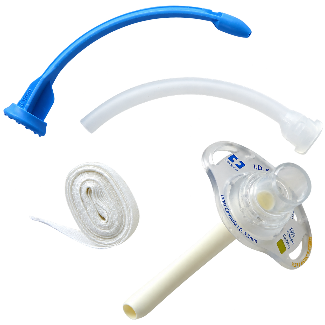
TR-T01 Component study 4UN65H
TR-T01 · Product photograph · date unknown
Four separate pieces. One working device. Follow the curve of the tube, then find the liner, insertion aid and securement ties.
Shiley device, Covidien branding. Photograph supplied by the owner; photographer and original source unconfirmed. Background removed with AI assistance; original retained.
Look closer ↗Original photograph ↗From the outside in
Start with the flange and connector, then follow the curved outer tube. The inner cannula fits inside it. The blue obturator belongs to insertion, not breathing; the ties belong to securement.
TR-T02 · Moving image study
A closer look · 1 min 47 sec
TR-T02 · Device demonstration film
You’ve met the individual components. Now watch how they come together. Follow the connections between the parts you can see—and the structures they lead to.
Look for a familiar component. Follow what the demonstrator does with it.
Owner-selected film · hosted on VideoPress. Original footage and sound preserved. Maker and recording date unconfirmed.
Open original film ↗Device details may differ from the cuffless specimen above. Caption and transcript review pending.
This specimen is cuffless. Beside it, another design adds a small inflatable cuff—and a separate system with a different job. Let’s follow that system next.
02 · Follow the cuff system →Gallery 02 · Room 02
A patient with a tracheostomy is struggling to breathe. As you assess and oxygenate, identify the tube: does it have a cuff, and can it provide a seal for ventilation? Cuff presence alone does not establish that the airway is working.
Start with the small balloon beside this Shiley. Follow its line to the tube, then explore the cuff. Together, these parts form a system separate from the breathing lumen.
TR-T03 · Shiley Flexible XLT · Cuff system
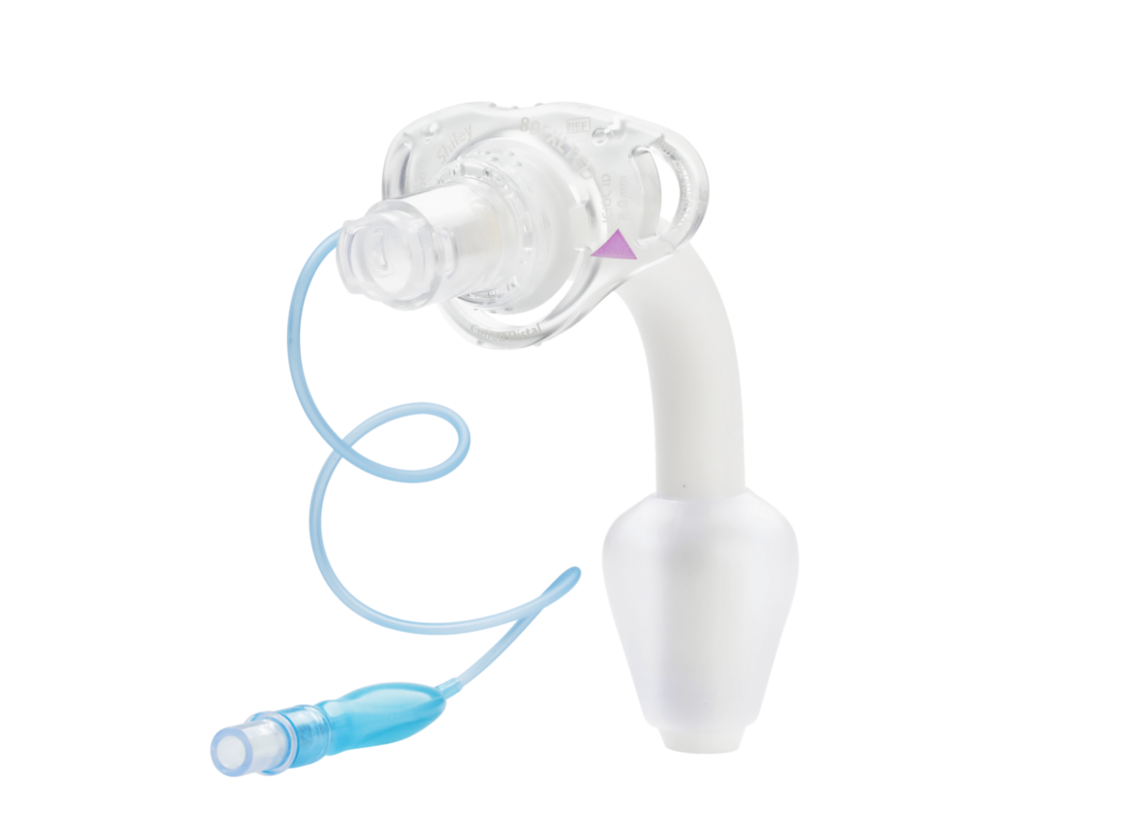
TR-T03 · Interactive product photograph
Choose a component to locate it on the specimen. This is a cuffed Flexible XLT—an extended-length model, not the standard Flex. The photograph shows the external system; it does not reveal the internal inflation channel.
Manufacturer product photograph · Medtronic · date unknown. Original image preserved; PAC identification overlays.
Inspect the cuff system ↗Two separate paths
Functional paths—not an anatomical drawing. The photograph does not show the internal inflation channel.
The seal
An inflated cuff limits air escaping around the tube during positive-pressure ventilation. A cuffless tube has no cuff seal, but may be appropriate for a patient breathing independently.
The cuff does not prove correct tube position or patency, secure the tube by itself, or eliminate aspiration.
The pressure
The pilot balloon is not a pressure gauge. Use a cuff manometer—not balloon firmness or a fixed syringe volume. Excessive pressure can injure the trachea.
Follow the exact device instructions and local policy for pressure targets and checks.
The leak
A leak can reflect inadequate inflation, cuff damage, poor fit, high ventilation pressures, or partial displacement. Find the cause rather than repeatedly adding air.
We can now distinguish a cuff from the system that fills it. But two cuffed tubes can still be quite different. The next clues are written on the flange.
03 · Read the dimensions →Gallery 02 · Room 03
The markings on a flange can look like little more than a catalog reference. Read them alongside the tube, and they become a description of its geometry: the space inside, the diameter outside, and the length along its curve. A familiar size number tells only part of that story.
This cuffed Shiley Flex example is a different model from the cuffless specimen in Room 01. Let’s read it closely, then compare how a change in length alters the shape we have come to recognize.
TR-T04 · Shiley 6CN75H · Flange study
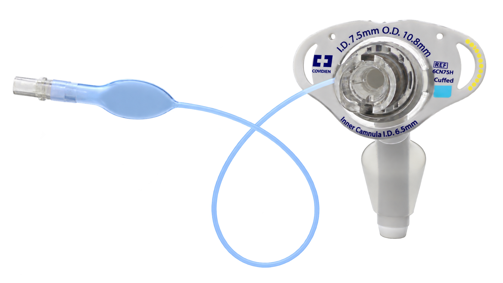
TR-T04 · Interactive photographic study
Choose a description to locate its printed marking on the flange. These highlights identify labels; they do not measure the opening in the photograph. The fitted inner cannula partly conceals the outer-tube lumen.
Covidien/Shiley device · still supplied by the owner, original filmmaker and date unconfirmed. Background extraction and image refinement with AI assistance; consult the original for documentary detail.
Inspect the markings ↗ · Original still ↗The flange gives us more than a size. Read its reference one part at a time.
O.D. 10.8 mm describes the diameter outside the tube—not the space available for airflow. These markings describe the specimen above; other models have their own dimensions and component requirements.
Internal diameter describes the lumen. With an inner cannula fitted, use the diameter available through that liner. External diameter describes the outside of the tube; it is not the breathing space.
Diameter alone cannot describe a tube’s shape. Compare its length and curve, then distinguish extra length before the bend from extra length beyond it.
Accommodates greater distance between the skin and the trachea.
Changes intratracheal reach. It is not the same adjustment as proximal extension.
TR-T05 · A study of tube geometry
Start with the familiar Flex, then look at the extended-length design. Below, the anatomical plates show why the position of that extra length matters.
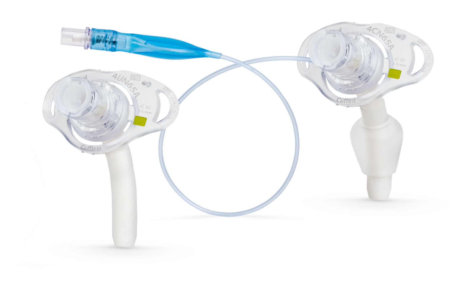 Inspect the object ↗
TR-T05A · Product photograph
Cuffless 4UN65A at left; cuffed 4CN65A at right. Follow the pilot line to the cuff added around the right-hand tube.
Manufacturer product photograph · Medtronic · date unknown.
Inspect the object ↗TR-T05B · Product photograph
The longer intratracheal segment changes the tube’s reach. This is a Flexible XLT, a different product family from the standard Flex beside it.
Manufacturer product photograph · Medtronic · date unknown.
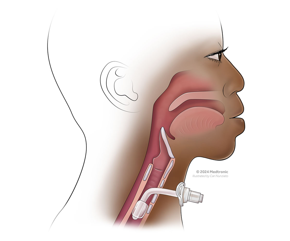 Inspect the object ↗
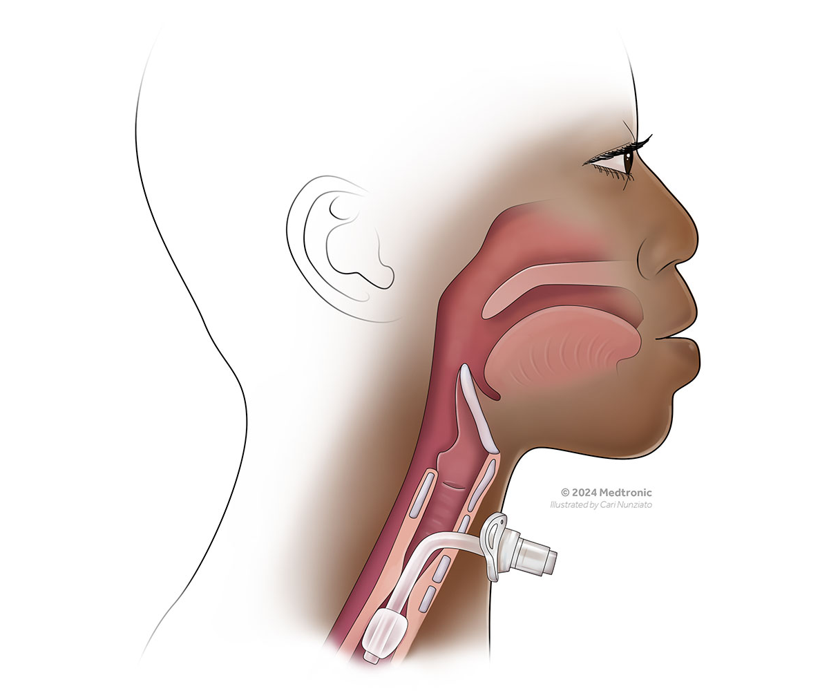
TR-T05C · Anatomical illustration
Follow the tube from the flange toward the trachea. Here, the extra length accommodates a greater skin-to-tracheal-wall distance.
Illustrated by Cari Nunziato · © 2024 Medtronic.
 Inspect the object ↗
TR-T05D · Anatomical illustration
Compare the segment beyond the bend. Here, the extension sits within the trachea rather than spanning more tissue in front of it.
Illustrated by Cari Nunziato · © 2024 Medtronic.
The markings help us recognize the tube in front of us. Now return to its entrance: what happens when another object is fitted to that connector?
04 · Study what connects →Gallery 02 · Room 04
A tube rarely sits alone. At its entrance, an attachment may help conserve warmth and moisture, connect breathing equipment, or change where air can travel. Follow a breath through the assembled device to see what each attachment changes.
As you compare the objects below, trace inspiration and then expiration. Pay particular attention to the speaking valve and the cap: this is where our study of the tube leads us back to the anatomy above it.
TR-T06 · Four objects at the connector
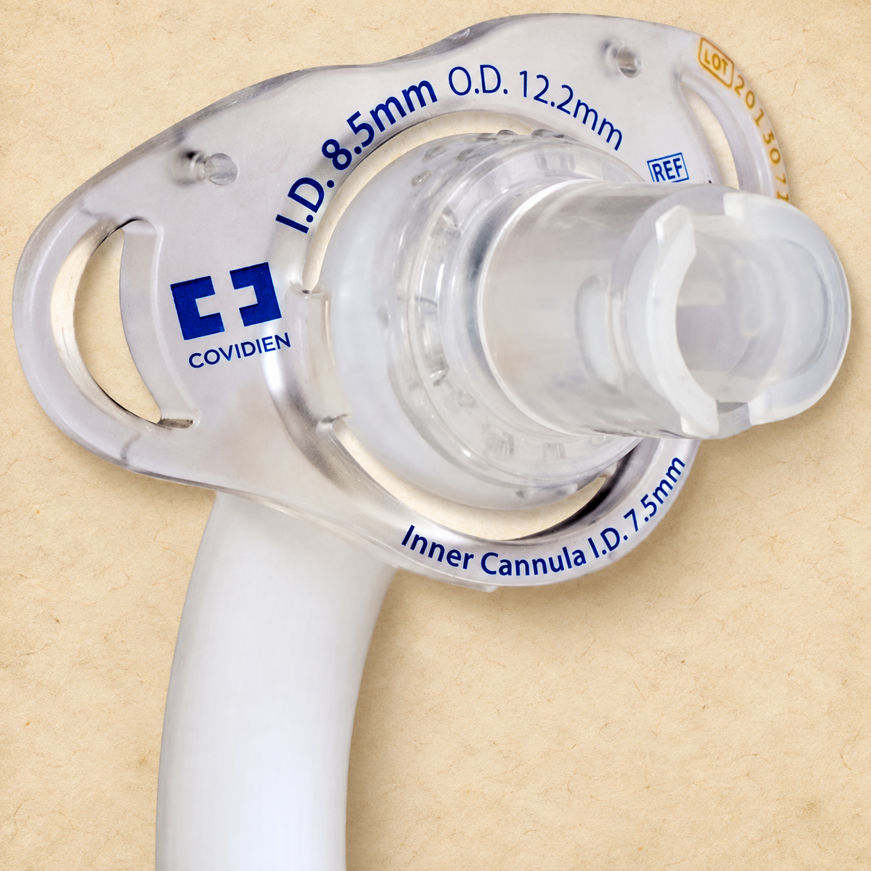
Inspect each object, then compare where a breath enters and leaves. Photographs are not to scale.
 Inspect the object ↗
TR-T06A · Product photograph
Shiley Flex · integrated connector
The central connector is the entrance to the tube lumen. Compatible ventilation equipment connects here; it is not the pilot-balloon valve.
In and out through the tube
Integrated 15-mm connector on adult Shiley Flex. Verify the exact tube and equipment instructions.
Owner-supplied photograph · AI-assisted parchment treatment; PAC identification arrow. Original source/date unconfirmed.
Medtronic · Flex ↗ · Original photograph ↗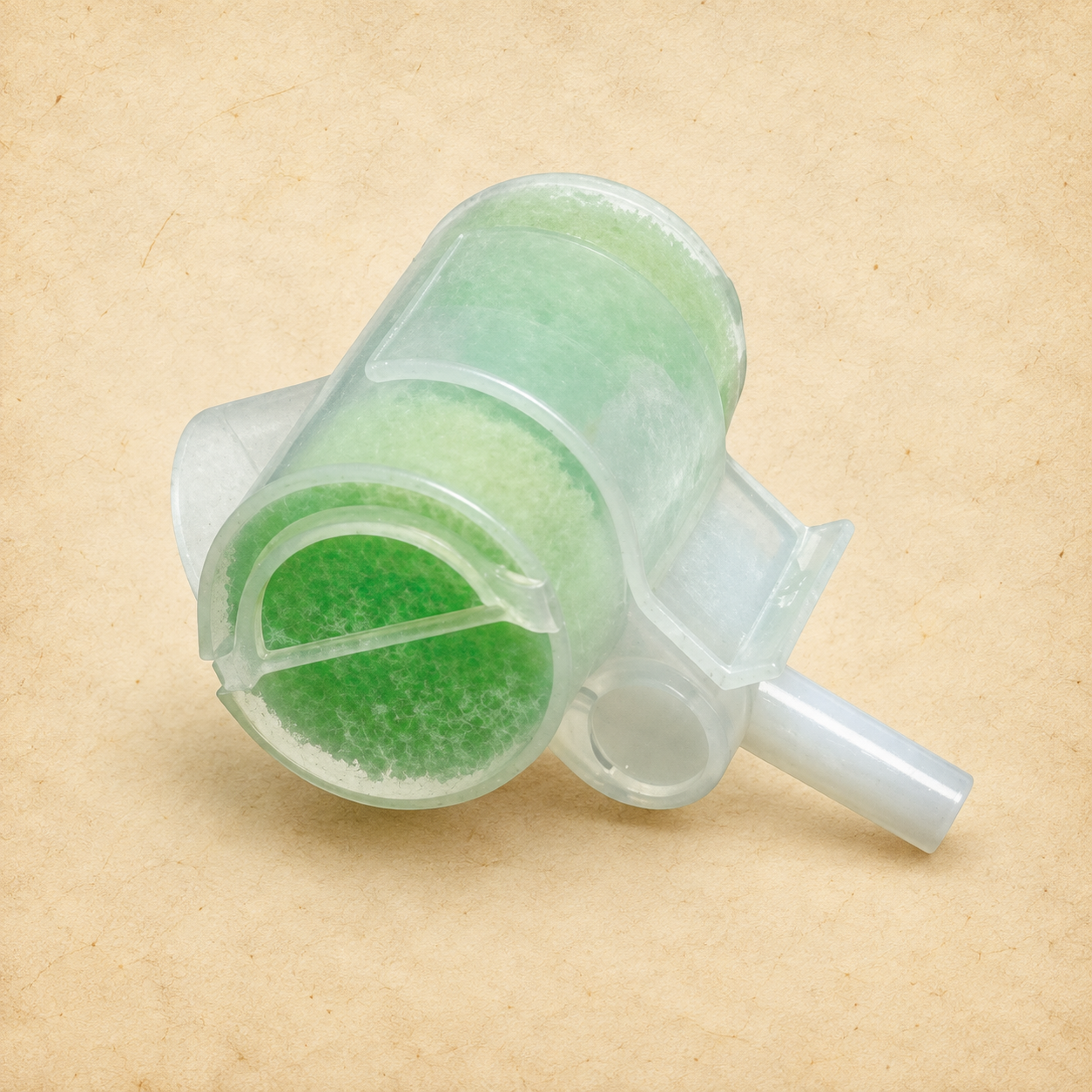 Inspect the object ↗
TR-T06B · Product photograph
Hydro-Trach T Mk II · 1873000
This HME helps retain exhaled heat and moisture for the next inspired breath. It is designed for spontaneously breathing tracheostomy patients—not a one-way speaking valve.
In and out through the HME
15-mm female connector matches the standard 15-mm tube interface. This is connector compatibility, not blanket clinical approval; check the HME instructions and patient requirements.
Intersurgical Ltd. source photograph · AI-assisted parchment treatment · date unknown.
Intersurgical · Hydro-Trach ↗ · Original photograph ↗ Inspect the object ↗
TR-T06C · Product photograph
Shiley speaking valve
Inspiration enters through the tube. On expiration, the valve closes and air must travel around the tube through a patent upper airway. The hinged cover is not a decannulation cap. A cuff must be fully deflated; upper-airway patency and tolerance must be assessed.
In through tube · out through upper airway
Fits the 15-mm tracheostomy connector. Confirm the exact valve IFU and approved tube configuration; intended for alert, awake, independently breathing patients.
Medtronic source photograph · AI-assisted parchment treatment · date unknown.
Medtronic · valve guide ↗ · Original photograph ↗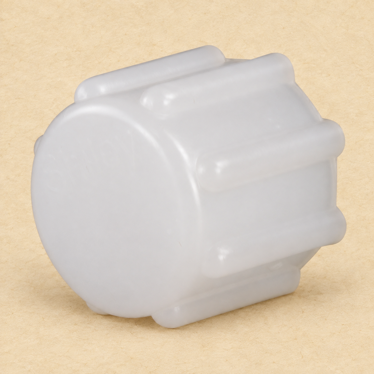 Inspect the object ↗
TR-T06D · Product photograph
Shiley white 15-mm CAP
A cap closes the tube opening in both directions. Inspiration and expiration must use the upper airway. This white CAP is not the red DCP or DDCP plug. Use only under an assessed capping plan, with any cuff fully deflated and a patent upper airway.
In and out through upper airway
Medtronic’s product guide lists CAP for Shiley flexible tubes. Match the exact model and approved capping plan; legacy plugs are not interchangeable.
Owner-supplied photograph · AI-assisted parchment treatment.
Medtronic · accessory guide ↗Original photograph ↗The speaking valve and cap bring the upper-airway route back into the device study. Revisit tracheostomy and laryngectomy anatomy if that route is unclear.
A fitting connection is not permission to use it. Speaking-valve and capping use require clinical assessment of the upper-airway route and tolerance. A cuff must be completely deflated when these are used with a cuffed tube. Do not place a valve or cap on a patient merely to explore its function.
You can now recognize the tube and its attachments. Before entering the cases, look beyond the device: is the bedside ready for the patient who depends on it?
05 · Prepare the bedside →Gallery 02 · Room 05
Before a patient needs an airway decision, the room needs to be ready. The next person through the door should be able to identify the airway, find the right equipment and know that it works.
Read the airway information, then look across the equipment. What belongs here depends on the patient—not simply on the word “tracheostomy.”
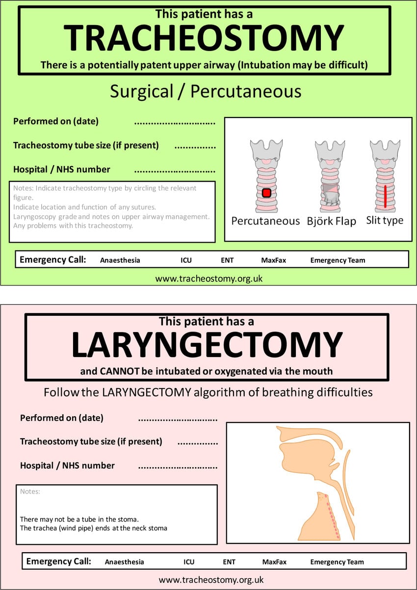 Read the signs ↗
TR-T10 · Paired clinical signs
Tracheostomy: the upper airway may be connected, but patency and intubation difficulty must be documented. Total laryngectomy: the lungs connect only to the neck stoma; oxygen or intubation through the mouth or nose will not reach them.
The sign identifies the airway. The next object records its history. At the bedside, use the current locally approved sign completed for the patient.
National Tracheostomy Safety Project · date unknown. Owner-supplied reproduction from ResearchGate; original colors, wording and proportions retained.
PAC teaching collection · Record 011
Fictional teaching example—not a bedside form.
01 Sep 2026 · 09:30
Surgical tracheostomy
The date of the opening—not the date of the tube now in place.
Shiley Flex · 6CN75H
Cuffed · outer-tube ID 7.5 mm
OD 10.8 mm · inner-cannula ID 6.5 mm
Exact reference and dimensions belong together.
First change completed
10 Sep 2026 · 10:00
Latest change: 24 Sep 2026 · 14:00
Keep both events separate from stoma creation.
Upper airway: connected; prior difficult oral intubation.
Stay sutures: none present.
Full plan: bedside copy + chart.
Emergency contacts: airway response team / ENT via local emergency system.
Teaching example—no operational contact numbers.
Fictional record reviewed 28 Sep 2026 · No real patient information
Choose a question to locate the information. The complete record stays visible.
TR-T11 · Interactive fictional airway record
Age informs risk; it does not prove tract maturity. Compare creation and change dates, then carry the exact tube information forward when selecting a spare.
Created by the Protected Airway Collaborative, 2026. Illustrative record with invented dates and history; not a clinical form or a prescribed tube-change schedule. Tube diameters match the 6CN75H flange study in Room 03.
Compare the tube’s flange markings →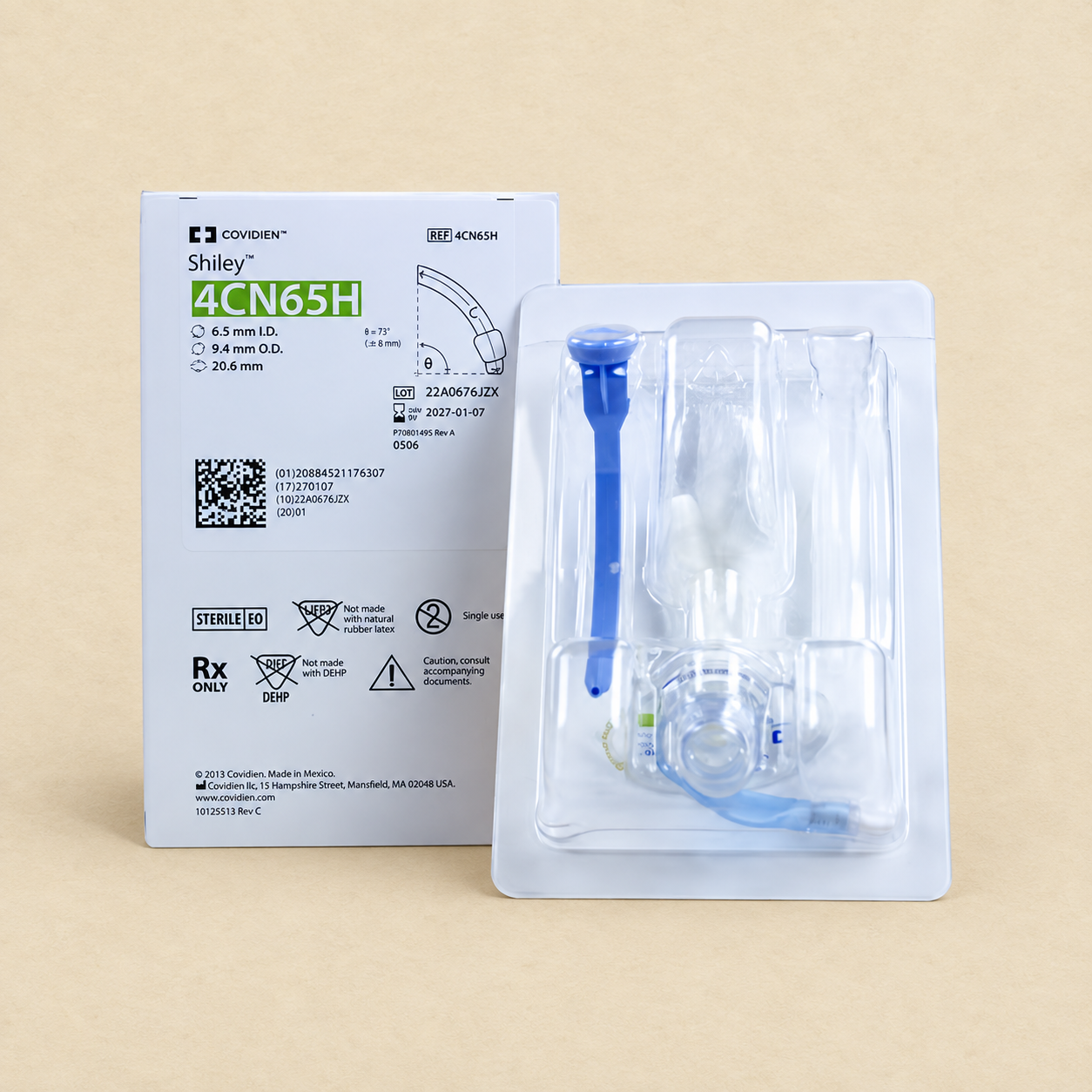 Inspect the replacement set ↗
TR-T12 · Replacement-tube photographic study
This Shiley 4CN65H set shows how a replacement arrives. It is an example—not the spare specified by the fictional record above. Match the patient’s exact tube requirements, including length and design.
Keep suitable same-size and smaller spares with matching components. Next, look at how those supplies travel with the patient.
Shiley / Covidien device · owner-supplied photograph · date and photographer unknown. AI-assisted parchment presentation; small package markings may differ from the source. Illustrative only—not a specification or labeling reference. Original photograph available below.
Original photograph ↗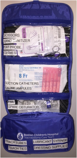 Inspect the bag ↗
TR-T13 · Transport-kit photograph
A labeled pocket makes an item easier to find. Before departure, check the contents against this patient’s tube and transport plan—not the photograph alone.
Alongside the bag: functioning portable suction, adequate oxygen and appropriate ventilation equipment; monitoring, airway information and the patient-specific emergency plan travel too.
Carry saline only for uses specified in the care plan or local protocol. Do not interpret its presence as an instruction to instill saline into the tracheostomy to loosen a plug; routine saline instillation during suctioning is generally avoided.
Recheck the kit before transfer and replenish after use. Equipment availability does not replace trained assistance or the patient’s emergency plan.
Owner-supplied photograph · bag marked Boston Children’s Hospital Tracheostomy Care Team; photographer and date unknown. Original labels and photograph preserved. Pediatric example: the visible 8 Fr catheter is not an adult sizing recommendation. The list describes readiness items, not verified contents of every pocket.
References · St George’s · emergency equipment ↗ · NTSP · transport readiness ↗ · AARC · suctioning ↗
The signs identify the airway; the record and equipment make preparation patient-specific. The cases now bring those details into a decision.
Continue to Emergency Cases →Or consult the optional reference cabinet ↓Optional · Reference cabinet
Medtronic/Shiley is the teaching reference here, not a claim that every tracheostomy tube works the same way.
Fenestrated tubes and devices with an additional above-cuff suction lumen require their own component study. A fenestration is an opening in the tube wall; a suction lumen is a separate channel. Neither should be inferred from a generic tube illustration.
Comparative illustration in preparation · TR-T09. Exact models and device instructions must be confirmed before depicting flow or manipulation.
Optional studies of inner-cannula care, device codes, cuff pressure and voice prostheses. Open what you need; the emergency cases do not require a detour here.
TR-T07 · Paired component study
Find the inner cannulas in each set. The manufacturer’s labels tell us which design we are looking at; appearance alone does not.
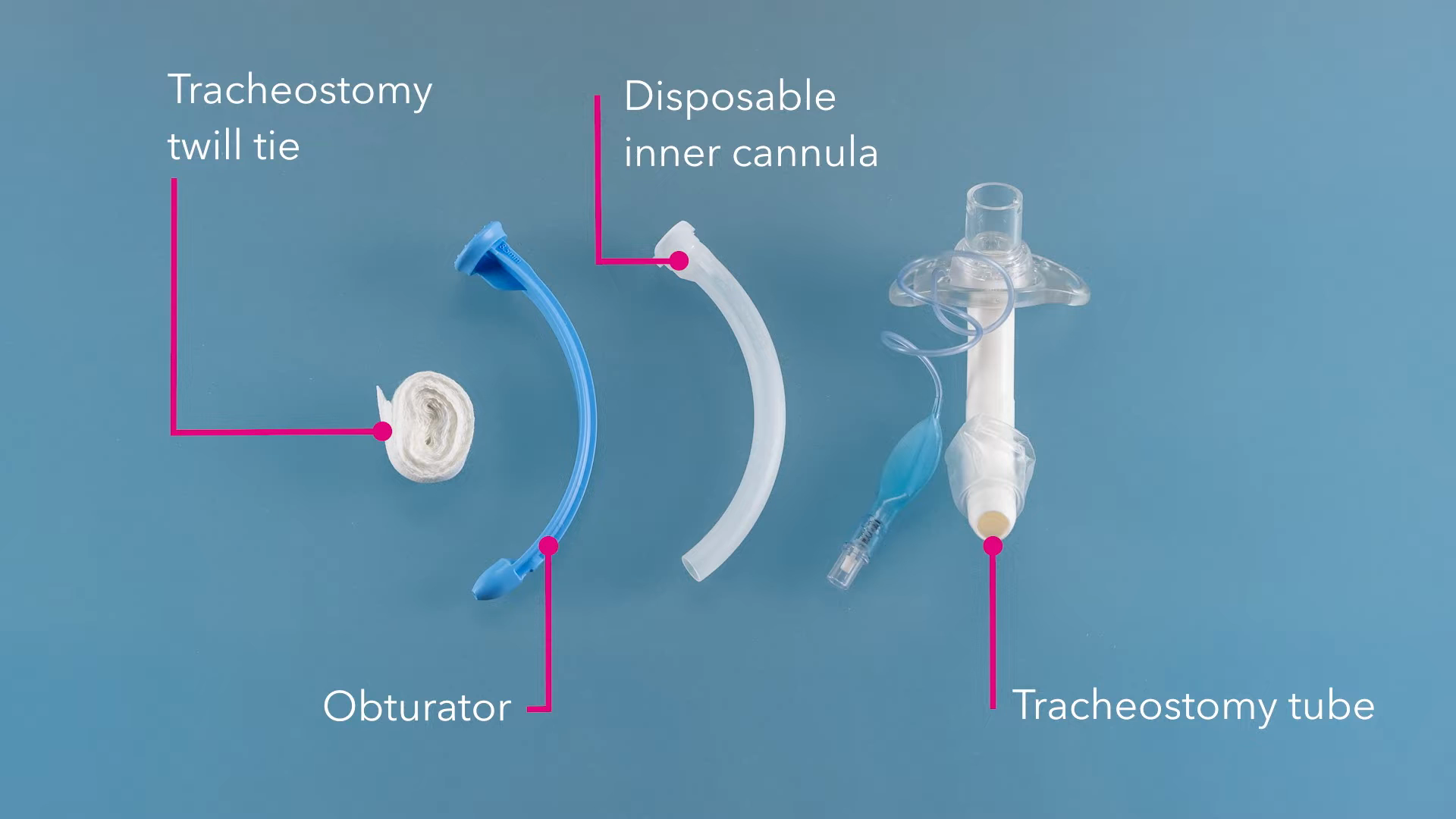 Inspect the object ↗
TR-T07-A · Manufacturer training still
One disposable liner is identified beside the obturator and outer tube. Match the exact component to its tube before replacing it.
Medtronic Surgical · Cleaning and care: Shiley™ flexible tracheostomy tubes · 2023 · 0:45. Original frame retained.
Source film ↗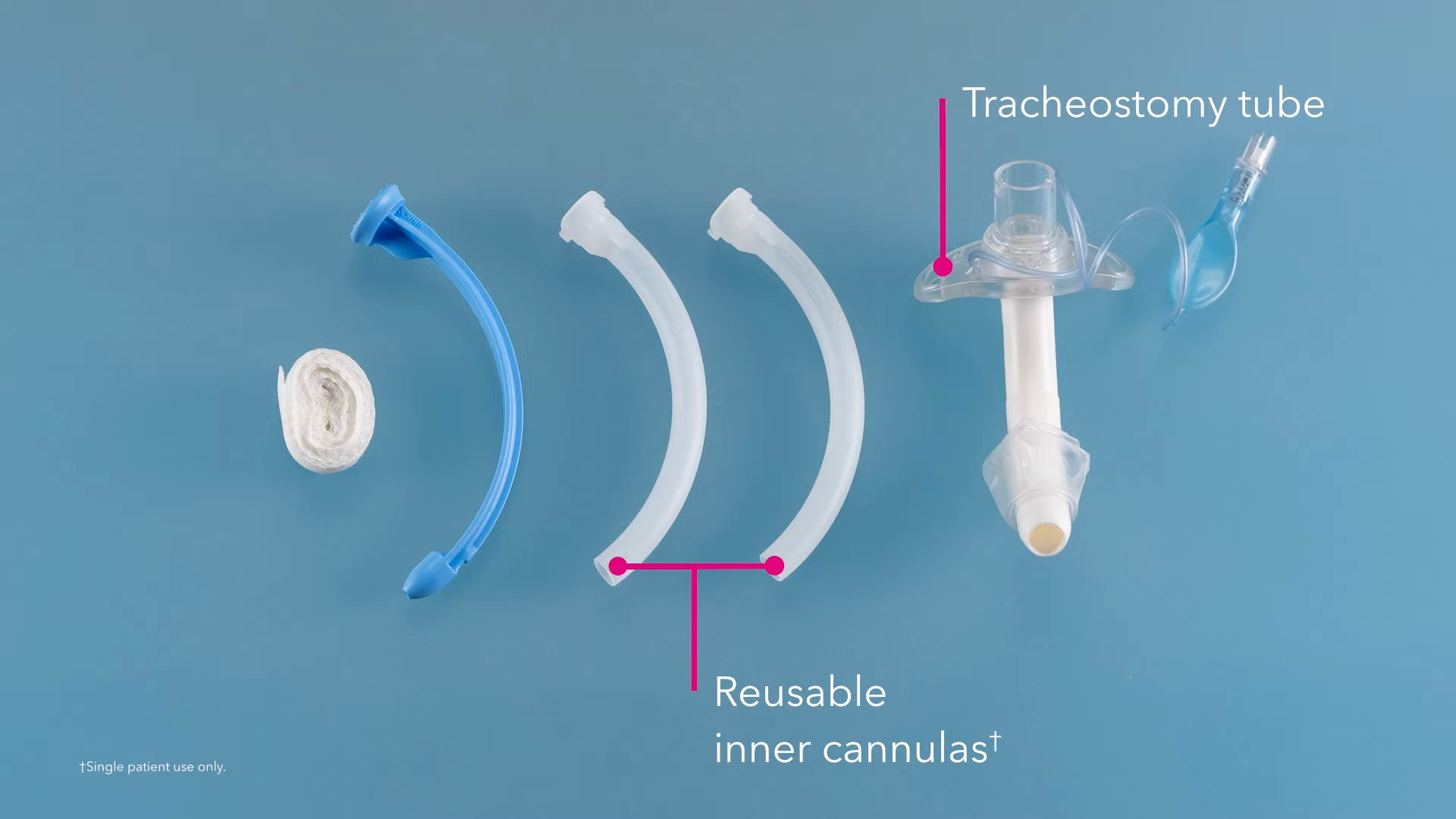 Inspect the object ↗
TR-T07-B · Manufacturer training still
Two reusable liners are identified in this set. Reusable means care according to the device instructions for the same patient—not reuse between patients.
Medtronic Surgical · Cleaning and care: Shiley™ flexible tracheostomy tubes · 2023 · 2:15. Original frame retained.
Source film ↗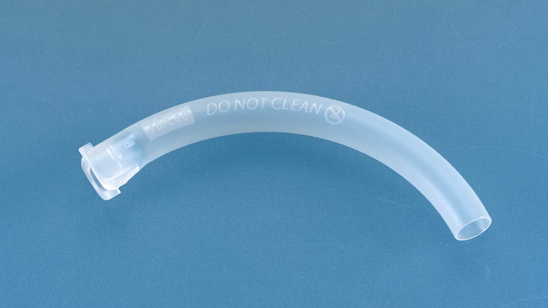 Inspect the object ↗
TR-T07-C · Manufacturer training still
The disposable cannula carries the instruction “DO NOT CLEAN.” This close-up makes a small but consequential distinction visible.
Medtronic Surgical · Cleaning and care: Shiley™ flexible tracheostomy tubes · 2023 · 1:15. Original frame retained.
Source film ↗Documentary teaching frames: original blue backgrounds and manufacturer annotations preserved. Images are not to scale; these views do not establish exact model compatibility.
TR-T07-D · Manufacturer reference study
Read the final letter of the Shiley™ Flex reference code. It identifies the inner-cannula type supplied with that tube.
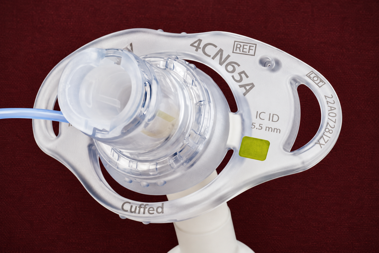 Inspect the flange ↗
TR-T07-D · Photographic flange study
This example reads 4CN65A. Its final A identifies a disposable inner-cannula configuration. The two codes below compare size 6 models; they are not the model pictured.
Shiley / Medtronic device · owner-supplied image. AI-assisted background treatment and image refinement; original available for fine-detail verification.
Original photograph ↗6CN75R
Clean according to the exact model’s instructions, for the same patient.
6CN75A
Replace rather than clean for reuse.
These are tube reference codes, not interchangeable inner-cannula part numbers. Confirm the matching component and its instructions.
Reference · Medtronic · July 2025 · US-RE-2500105. Read the manufacturer’s code key ↗
TR-T08 · Manufacturer product photograph
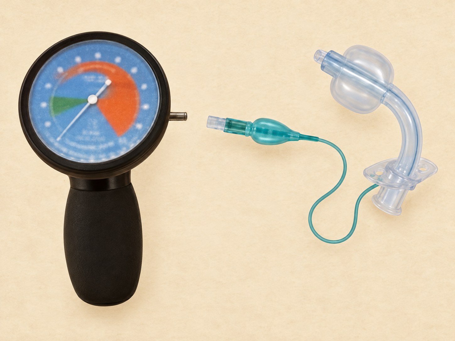
20–30 cmH₂O is a common adult target when cuff inflation is required. Follow the exact device instructions and local policy; recommended ranges vary.
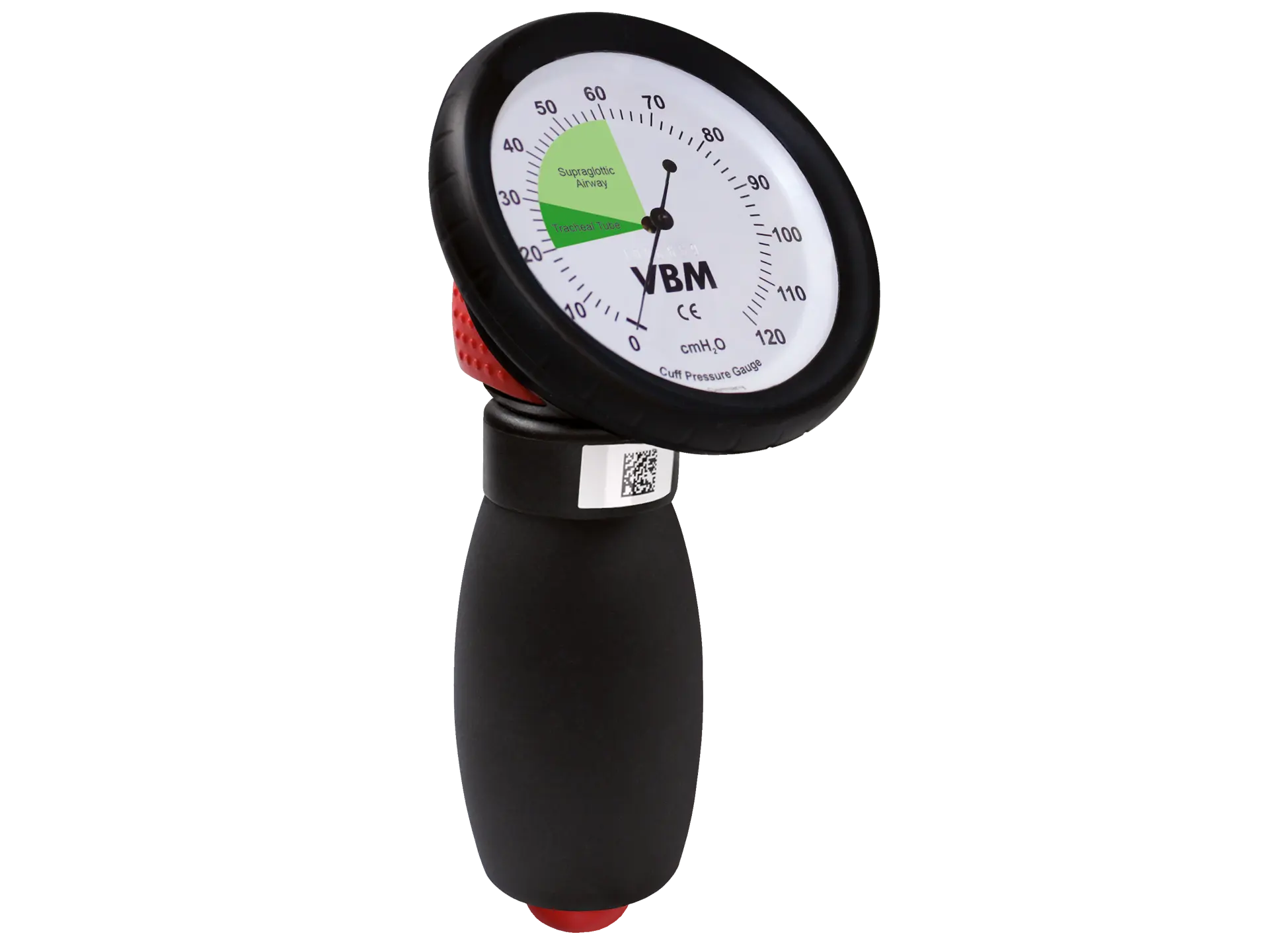 Inspect the instrument ↗
 Inspect the companion study ↗
TR-T08-B · Manometer and cuffed tube study. Owner-supplied image; creator and date unknown. AI-assisted enlargement and parchment treatment; not a readable pressure scale or model-specific connection guide. View original ↗
Even a correctly inflated cuff does not eliminate aspiration. A persistent leak needs assessment—not simply more air.
Connect to the cuff inflation valve, directly or through the specified connecting tubing—not to the 15-mm breathing connector.
VBM Medizintechnik GmbH · Universal cuff manometer · photograph date unknown. Original transparent manufacturer image; PAC parchment mount. No connected Shiley setup is depicted.
VBM · adult pressure range ↗ · NTSP · cuff risks ↗ · St George’s · monitoring ↗
Keep the exact tube code and matching component information with the care plan.
Cleaning agents, replacement intervals and handling steps must follow the exact device instructions and local policy. This gallery introduces the equipment; it does not authorize patient procedures.
Device note · Voice and swallowing
A tracheoesophageal voice prosthesis after total laryngectomy is a different device from a tracheostomy speaking valve. Speech after laryngectomy may also use esophageal speech or an electrolarynx; speaking does not establish a normal airway connection.
The digestive and respiratory routes are separated after total laryngectomy, but swallowing problems can still occur. A voice prosthesis can leak through or around the valve. Swallowing and communication needs require individual assessment.
Device comparison object in preparation. This note does not provide fitting, valve-use or troubleshooting instructions.
Return to airway function →The next space · Emergency Cases
The cases bring the airway anatomy and device together. Make your next decision before hearing the explanation.
Exhibit 03 · Emergency Cases
Choose a case, make your next decision, then compare your reasoning with the debrief.
Playback could not start. Open the introduction directly →
PAC Poster 613 · Captioned audioscape
1:35 · Sarah introduces the cases to a junior clinician. Listen, then choose your first case.
Created by the Protected Airway Collaborative, 2026. AI-assisted poster; fictional dialogue with ElevenLabs synthesized voices and designed room ambience.
View the complete poster ↗[Quiet simulation-room ambience]
Sarah · Senior clinician Welcome to the tracheostomy safety lab. You've explored the airway and the equipment. Now let's put them together with a patient and a problem to solve.
Hale · Junior clinician All right. Where do I start?
Sarah · Senior clinician Choose an available case. Meet the patient, listen to what's happening, and decide what you would do next, before you hear the explanation.
Hale · Junior clinician And this trainer? We get to use that too?
Sarah · Senior clinician Exactly. You can work through the decisions online. For the hands-on cases, follow the setup instructions and use this trainer, on your own or with a partner. If you're working together, have your partner watch what you do and listen to your reasoning. Then switch.
Hale · Junior clinician Okay. But what if I get stuck?
Sarah · Senior clinician Then you've found something worth practicing. Pause, look it up, and try again. This is a safe place to be uncertain. Much better here than discovering that uncertainty with a crashing patient.
Hale · Junior clinician So I can come back and try the same case again?
Sarah · Senior clinician Absolutely. The useful question is: what will you do differently on the next attempt?
Hale · Junior clinician And when I've worked through them, we can go over how I did?
Sarah · Senior clinician Yes. Let me know. During your rotation, we can review the cases together, or you can demonstrate your approach to me or another attending. We'll talk through your decisions and work on anything that still needs attention.
Hale · Junior clinician That sounds a lot better than waiting for my first emergency.
Sarah · Senior clinician That's the idea. A more practiced approach when a real patient needs you. Go ahead, scroll down and open the first case.
[Room ambience fades]
Practice Studio · How to use this space
The case gives you a patient and a problem. The trainer gives your hands a place to work. Start with an available case below; use its decision pause to say what you would do, then compare your reasoning with the explanation.
When a hands-on setup is available, bring that same case to the trainer. Read the patient’s story on screen, set your phone or tablet aside for the attempt, and return for the debrief.
Say your assessment and next action aloud before revealing the explanation. After the debrief, return to the decision point and try again with one deliberate change.
Available now: Case 01’s online encounter. Cases 02–06 and case-specific trainer setup packs are in preparation. Use the physical trainer only with the matching setup instructions and a local trainer orientation.
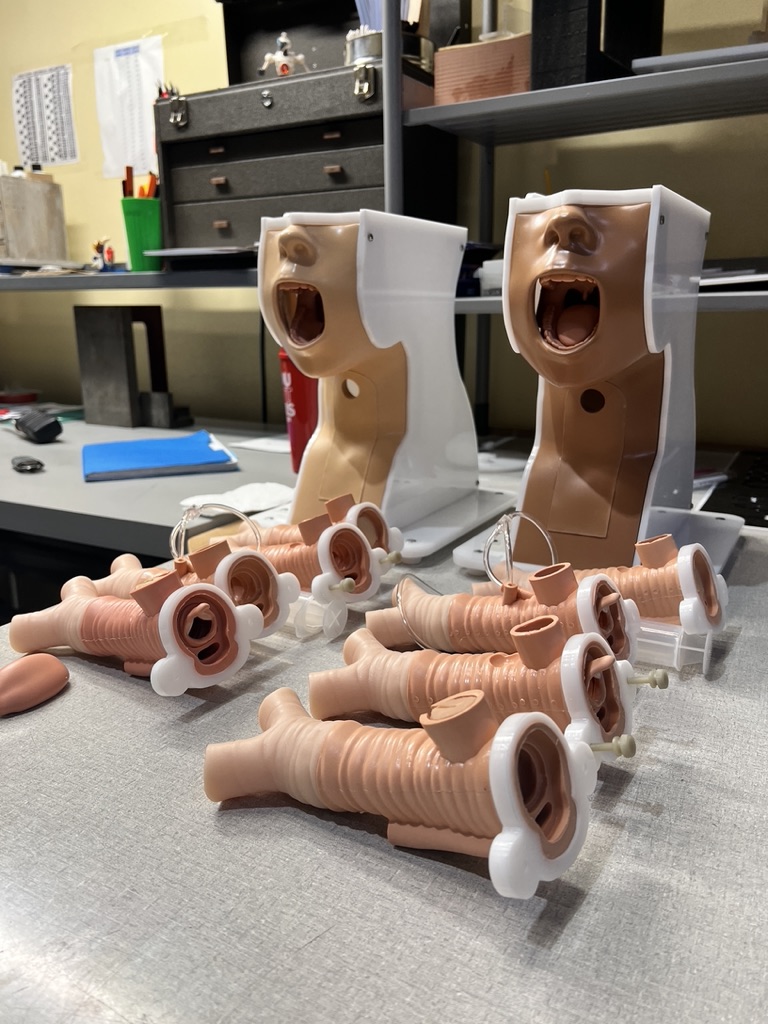
TR-C01 · Training-room photograph
The trainer bodies and separate airway inserts make the physical setup visible. Use the insert and equipment specified for your case, rather than choosing from appearance alone.
Source: owner-supplied Brian’s Resources collection. Photographer and date not recorded.
Look closer ↗Practicing with a friend or an education coach? Find the run card, partner roles and coaching instructions in Coach the cases.
Bedside scene
Listen to the exchange. Pause for your decision, then hear what happens next.
Open the caseBedside scene · In preparation
Listen to the exchange. Pause for your decision, then hear what happens next.
Coming soonBedside scene · In preparation
Listen to the exchange. Pause for your decision, then hear what happens next.
Coming soonBedside scene · In preparation
Listen to the exchange. Pause for your decision, then hear what happens next.
Coming soonBedside scene · In preparation
Listen to the exchange. Pause for your decision, then hear what happens next.
Coming soonBedside scene · In preparation
Listen to the exchange. Pause for your decision, then hear what happens next.
Coming soonInstallation Guide · educator route
Setup instructions, internal case identities, controlled cues, and reset states remain on the educator surface. The learner still receives the relevant clinical history and observations before the attempt.
Practice Studio · Case TR-OBS-01
Read the case. Start the clock when you begin. Stop to review your attempt and enter the case Gallery.
Open-page memory only. No saved record loaded.
The debrief
Less than seven days ago, in this case. Blind reinsertion could send the tube into soft tissue rather than the trachea, creating a false passage.
The attending stops the attempt. With the patient stable, the team calls ENT for guided replacement with a fiberoptic scope.
Check when and how the tracheostomy was formed. Seven days is not a universal clearance for replacement.
This scene illustrates a decision, not a reinsertion technique.
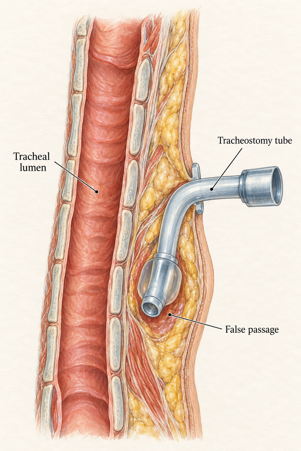
TR-C01-D02 · Anatomical illustration
Notice where the tube ends: in front of the trachea, outside its lumen.
Created by the Protected Airway Collaborative, 2026.
AI-generated illustration · Clinical review pending.
Diagnosis withheld until review
Owner-review prototype: final vignette, equipment, cues, and action wording await evidence, trainer-fidelity, scope, and named clinical review.
A labeled setup still will occupy this space once the exact trainer, objects, and starting arrangement are verified.
Case clock
Place the phone where you can see the clock. Keep your hands on the trainer.
The clock records an interval. It does not prove that the physical task occurred.
Case checkpoint · the clock has stopped
Check the actions you completed during the case. Record the attempt you ran—not the answer you know now.
The six controls prove the interaction and scoring model without presenting an unreviewed emergency sequence as instruction.
This is a self-reported practice record, not a competency assessment. Do not enter patient or identifying information.
By default, this page holds your responses only while it stays open. Gallery detours keep them; reloading or closing loses them. To retain them across reloads, choose tab storage below, then restore the saved record after reloading. Tab storage normally ends when the tab closes; shared or restored browser sessions may retain it. Copy what you want to keep and clear saved responses when finished. Nothing is sent to PAC or an educator.
Leave missed actions unchecked. Every attempt can enter the Gallery, including 0 / 6.
Studio exit · Gallery entrance
Case 02Opening the Gallery keeps your self-audit as recorded. Return to the anatomy and the tube with the case revealed.
Diagnosis reveal · Case 02
The Gallery now reconstructs the case through anatomy, the appliance, the observed failure, and the next attempt.
Debrief Room 01 · return to the source
Look again, with the case exposed
Compare the case with what you noticed, what you inferred, and what you did.
Archival teaching poster · clinical update in preparation.
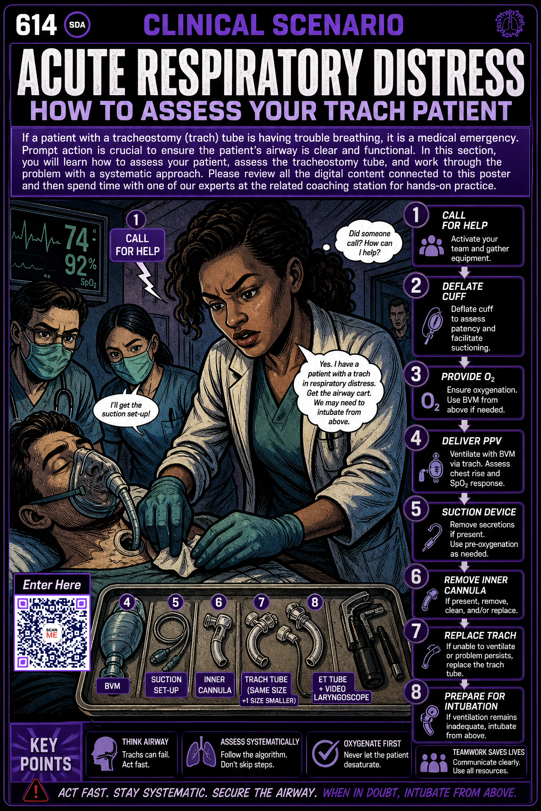 Archival scenario poster · post-attempt only
The poster preserves the inherited scenario while the case-specific debrief is rebuilt.
Reference only · rights, evidence, and clinical review pending.
Debrief Room 02 · reconstruct the mechanism
Return to the relationship that made this case difficult.
A restrained animation will connect the learner’s observed trainer response to the case mechanism without becoming an algorithm.
Moving diagram · 16:9 panorama · silent loop
Case-specific storyboard, evidence, and clinical review pending.
The scenario film belongs here, after the learner has committed to an approach and can compare another performance with their own.
Demonstration film · 9:16 portrait · captions and transcript
Inherited film audit, edit, rights, participants, and clinical review pending.
The reviewed sequence will show actions, observations, and decision points at a glance while keeping the complete clinical explanation in the adjacent label.
Five-part procedural sequence · 5:1 frieze
Exact action order, role boundaries, evidence, and named clinical review pending.
A learner-view object study will make the physical reset reproducible before the next attempt.
Numbered stills and physical labels · 1:1
Trainer state, equipment, cleaning, reset owner, and cold-start review pending.
Debrief Room 03 · Carry it into practice
Choose one decision or observation to revisit.
Reflection is optional. Keep a note if it will help your next attempt.
Continue from here
You can continue without a note. Your score records your account of the attempt; it does not establish competence.
Before you leave
The final Studio will name the observable finish, recovery cue, trainer reset, and next destination here. No click, clock, or score will stand in for that work.
Room 03 · Educator Room
One case. One observer. One clear change between attempts. Keep the learner’s hands on the trainer and the educator’s attention on the behavior.
One person is the clinician; the other is the coach. The coach reads the setup and cues, watches the attempt, and saves the explanation for afterward. Discuss what happened, reset, then switch roles.
From the case to the workbench
Open its setup sheet first. Find the specified trainer insert, tube and equipment; agree who will coach. If the setup or an item is missing, stay with the online encounter and ask the lab educator before proceeding.
Play or read the opening. Pause for your decision. On the trainer, perform the actions permitted by that case’s instructions and explain what you are looking for.
Open the explanation after you commit to an approach. The coach describes what they saw before offering advice. Choose one decision or movement to revisit.
Restore the trainer and equipment using the setup sheet’s reset and cleaning instructions. Repeat the part that needs work, or switch roles. Bring an unresolved question or a demonstration to your attending.
A completed practice attempt is a chance to review your approach, not a certification of clinical competence.
Brief
The tube is no longer where it was. The patient and station details remain case-specific.
Equipment, starting positions, roles, and finish line must match the validated trainer contract.
Observe
These are observation domains, not a released emergency action sequence.
Change one condition
No cue revealed.
Debrief and re-run
Ask what the learner noticed, what they believed the route was doing, and what evidence changed that belief. Then reset the trainer and run again.
Case-specific cues, acceptable variation, stop conditions, critical omissions, and escalation triggers require clinical and trainer-fidelity review.